
Native CAD · editable laminate definitions
Five aerospace cases, from CAD to reviewed plies.
Work through a spar, a native DLR nacelle, a transition web, a three-window shell and a curved fabric bracket. Start with the imported support, establish materials and datums, expand zones into detailed plies, then inspect, revise and retain the design evidence.
How to use the saved lifecycle
Make room for your part: use Design layout while editing and Inspect layout for the full-width model and section. Open Display controls for thickness magnification, layer gap, isolation and layup playback. Drag the divider above the thickness chart, or focus it and use arrow keys, to adjust its height. Present layout hides editing chrome for reviews and recordings; Escape leaves it. Full screen also removes browser chrome. Model browser and Properties restore each panel without discarding a draft.
- Open the workspace and choose Library in the left rail. In Aerospace design cases, choose a component and Start from CAD, its base laminate, or Inspect … plies. The links in each chapter download the same portable stages; open a downloaded project through File → Open file….
- In Model, inspect support faces and tooling groups. Use Materials and Rosette to read source, thickness basis, 0° direction and surface reference before changing a ply.
- Use Regions to inspect fixed support coverage and projected boundaries. Then read the ply table for each region, material, nominal thickness and declared angle. A zone footprint and a complete local overlapping stack are different records.
- Use Stacked layers at 1 · nominal, then Exploded layers, Layer gap, Build through ply and Isolate selected ply. 20 · inspect magnifies thickness for inspection. Show all plies restores the sequence.
- Choose Thickness section, its Projection and Along direction. Move Across using the coordinate output. Compare gauge on both sides of each drop and distinguish real holes from thin coverage.
- For a ply revision, select the record, change Angle (°), Region or the relevant reference in its editor, then choose Apply changes. Draft values do not alter the saved design until applied. Use Undo to recover the original during the exercise.
- Open Export → Summary… and Plybook… for area, material usage and declared stacking review. After an edit, regenerate any sheet marked STALE. Record unresolved findings against the design revision.
- Name a review copy, use Save project, wait for Saved, and reopen it through File → Projects. Use Export project… for a portable backup. For Export for AddPath… or Export HDF5…, read representation guards and the export summary before handoff.
To create a separate copy: first use Export project…, then open that backup through File → Open file…. Give the newly opened project a name and save it. Renaming an existing browser project alone updates its current record; it does not create another copy. Preserve the checked baseline before making an export copy or a review revision.
What to retain after each exercise
Project revision, support-face IDs, material source and basis, rosette, ordered ply IDs, boundary areas, local gauge samples, rule findings and a reopened portable copy. Browser saves belong to that browser and site; keep the portable file for transfer.
Case 01
Tapered wing spar
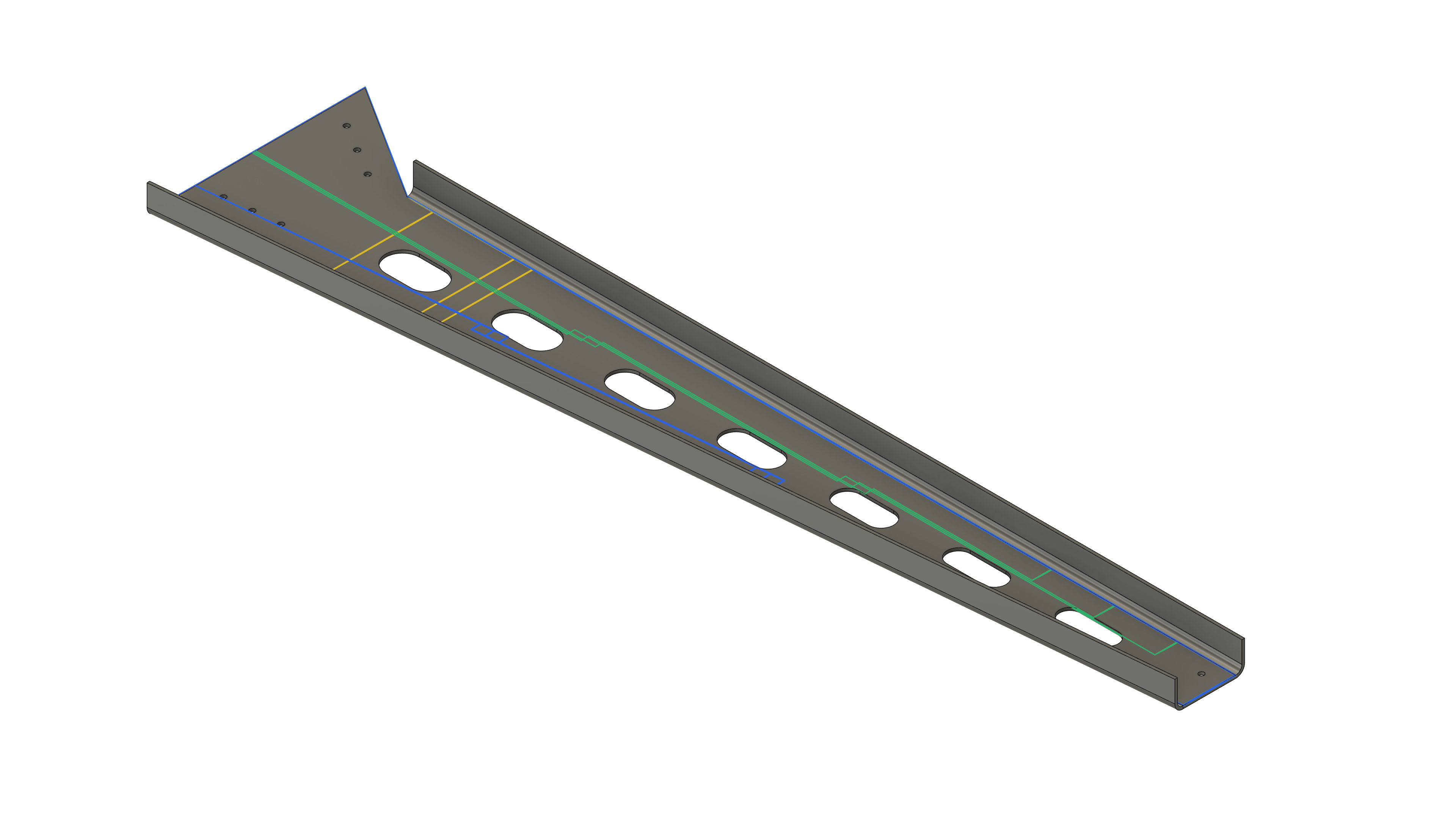
Original Fusion geometry and stack following the supplied spar feature reference. The carrier has curved C-section returns, seven obround openings and eight attachment holes; native ply sheets cover the web.
Download imported CADDownload base laminateDownload complete project
Identify the trimmed outer web
Start from CAD in the Aerospace design cases gallery. In Model, select F53 at Z=5.36 mm. Orbit to inspect both returns and the fifteen real voids. Keep F54, the inner web, out of the tooling group.
Review evidence: One outer web face measures 302,161.807 mm². Selecting both sides would duplicate the authored coverage.
Read the material and spanwise rosette
Open the eight-ply foundation. In Materials, inspect Carbon / HexPly M56 AS7 UD134 and its supplier provenance. In Rosette, read spanwise-x: 0° along +X, normal +Z. Read TOOL_TO_BAG order.
Review evidence: Each UD ply declares 0.134 mm cured thickness. The initial eight full-web plies total 1.072 mm.
Follow zones into detailed ply masks
Open the complete design and choose Regions. Inspect FULL-WEB and three nested packs of TOP-RAIL, BOTTOM-RAIL and ROOT-PAD. Select PLY-009 and PLY-011 to compare their matched +45°/−45° top footprint; inspect PLY-010 and PLY-012 for the other load paths.
Review evidence: Ten assigned CAD-clipped footprints carry forty records; one superseded root-pad region remains unassigned as review history. The second half mirrors the first half, including its boundaries. Sixteen plies ultimately cover the full web.
Build, explode and isolate
Use Stacked layers at 1 · nominal, then Exploded layers at 20 · inspect. Set a visible Layer gap. Use Build through ply or Play layup; select a rail ply and enable Isolate selected ply. Return to Show all plies.
Review evidence: The rail masks follow the stepped spar contour and retain the native voids. The separate Fusion ply sheets make the same web masks individually selectable.
Read gauge and review cutout interactions
In Thickness section choose XY, along X. Move Across using its Y coordinate output and compare the stepped coverage. Avoid sampling inside the obround voids. Inspect root-pad and top-rail terminations near openings.
Review evidence: Independent solid-web samples give 34 plies/4.556 mm at (100,200), 18/2.412 mm at (450,120), and 16/2.144 mm at (1300,200). The revised design still has ten internal rail-edge interactions with native voids.
Review the recorded root-pad revision
Inspect ROOT-PAD-3 revision1 in the completed project. Its end moves from X390 to X270 mm, leaving 24 mm to the first opening at X294 mm. Only mirrored PLY-020 and PLY-021 move to the new footprint. Save a separate copy for another boundary edit; recheck cutout margins, rules and gauge, then save, reopen and export.
Review evidence: The carrier, ply order and mirrored 90° pair remain unchanged. Ten assigned sequences and 3,016 solid-web sample stacks pass declared symmetry and balance. Twenty-seven edges remain below the chosen 10 mm teaching clearance threshold.
Edit and review exercise
Choose a third-pack root-pad or top-rail boundary that meets an opening. Propose a revised endpoint, record its clearance, and compare local gauge before and after. Keep the original design as the review baseline.
Case 02
DLR CRM-HL nacelle fairing
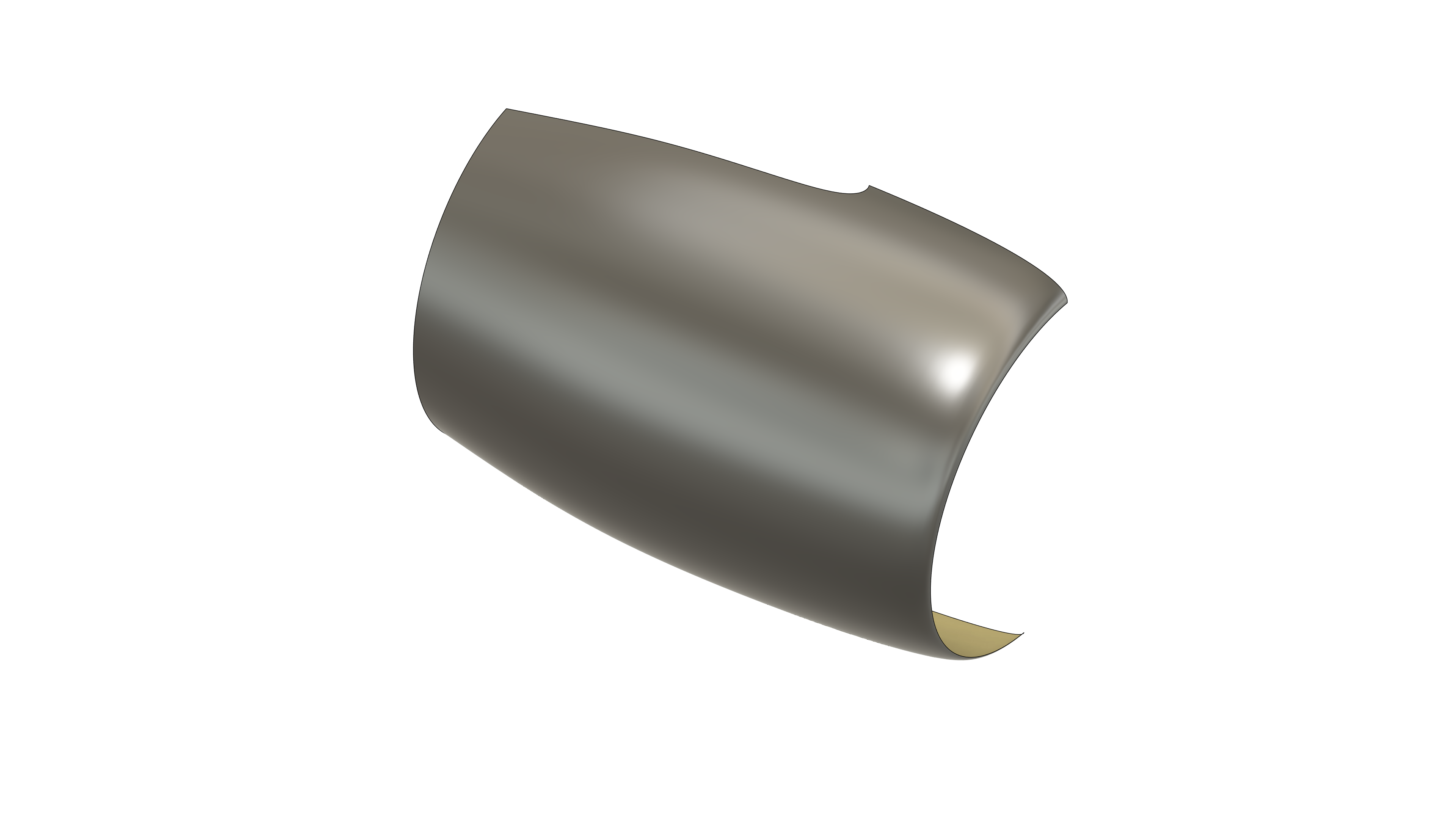
Genuine NASA-hosted DLR CRM-HL nacelle CAD, acknowledged to Schmidt & Wild, AIAA 2024-2851. The original outer fairing face is retained unchanged; the laminate and reinforcement boundaries are authored for this exercise.
Download imported CADDownload base laminateDownload complete project
Inspect the actual nacelle surface
Start from CAD. Orbit the imported fairing and identify F1, the extracted outer support. Compare the lip, aft interface and compound curvature with the native Fusion view below.
Review evidence: The lightweight project holds the original curved support surface. A downloaded aerodynamic surface alone does not prescribe an aircraft laminate.
Establish UD, woven and the engineering datum
Open the 26-ply continuous laminate. Read both Carbon / HexPly M56 AS7 UD134 and Carbon / HexPly M56 AS4 193PW in Materials. In Rosette, inspect the +X Primary engineering datum.
Review evidence: Twenty-four UD plies at 0.134 mm and two woven surface plies at 0.214 mm give 3.644 mm nominal continuous gauge. Woven angles refer to the fabric reference yarn direction.
Map three interface families into nested boundaries
Open the complete design. In Regions, compare Hinge load path, Inlet lip reinforcement and Aft interface reinforcement across drops 1–3. Their XZ boundaries are projected along Y and clipped to F1.
Review evidence: Ten regions carry fifty records. Each drop assigns hinge ±45°, inlet lip 90° and aft interface 0°; the mirrored half retains the same spatial masks.
Inspect individual curved plies
Choose Exploded layers and a moderate gap. Select one hinge ply, isolate it, and orbit to compare its curved footprint with its nested partner. Use Play layup and return to Show all plies.
Review evidence: Individual masks follow the actual CAD contour. UD and woven records remain distinct in the material and thickness columns.
Section the lip and interface transitions
Choose Thickness section with XZ projection, along X. Move Across by the displayed Z coordinate to cross a hinge or lip mask. Compare successive drop footprints and the baseline. Read any projection diagnostic before interpreting the plot.
Review evidence: The nominal gauge changes only where a reinforcement footprint covers the sampled support. Determine the active ply IDs at your chosen location rather than treating fifty records as fifty local plies.
Review a boundary revision and save
Save a named copy. Create a replacement interface footprint and reassign the affected matched and mirrored plies to it. Compare exact clipped area plus the local section. Regenerate the Summary and Plybook after the change, save, reopen and export the portable project.
Review evidence: The saved complete domain round trip preserves the native surface, ten regions, material references, rosette and all fifty plies. A family verdict alone does not establish strength or forming feasibility.
Edit and review exercise
Compare the first and third inlet-lip masks. Record their exact area, declared angle and sampled gauge. Move one vertex in a revision and identify every ply that shares that footprint before accepting the change.
Case 03
Zone-transition frame web
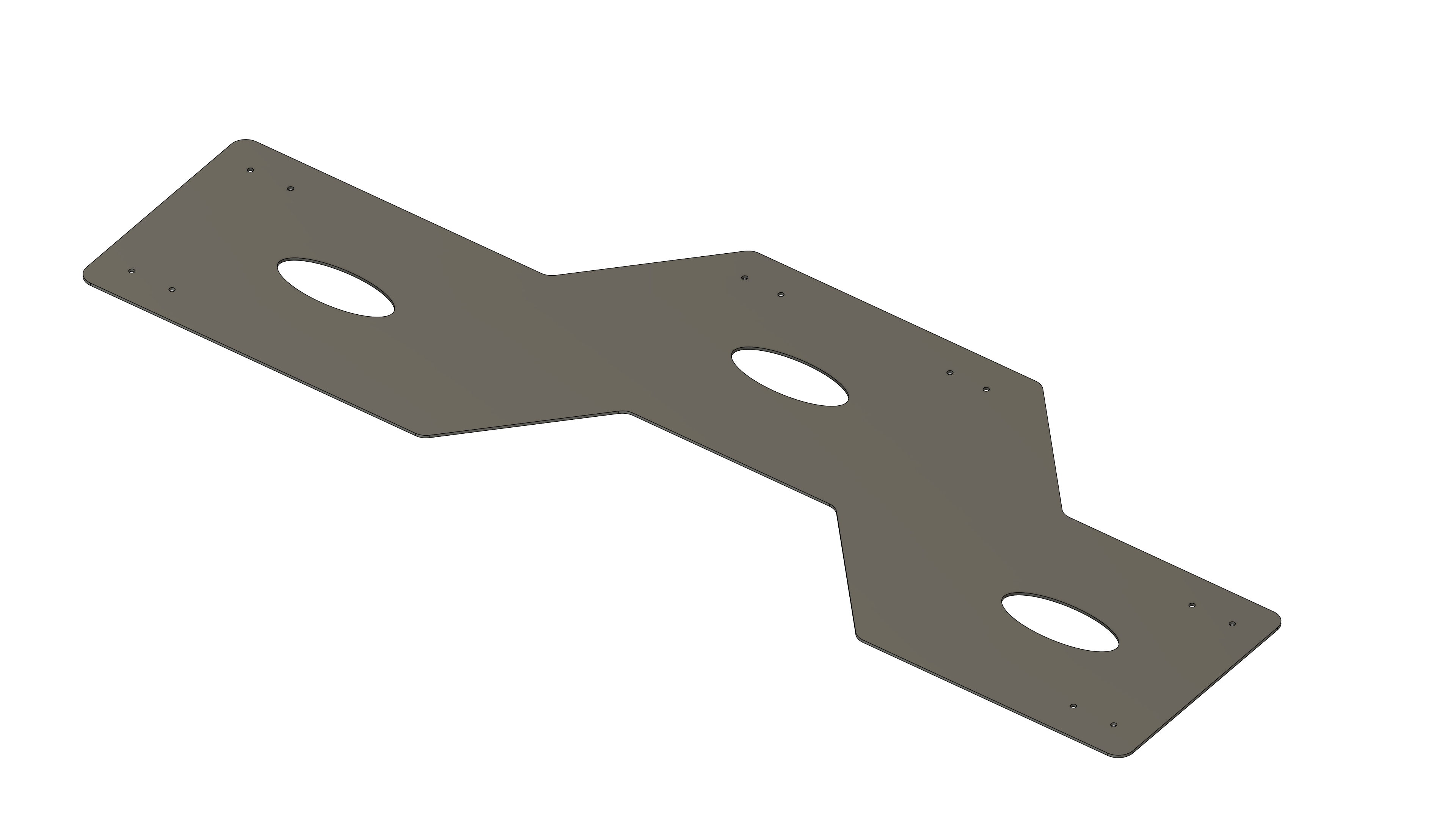
Original Fusion CAD follows the supplied transition-adjacency reference: a jogged plan load path, rounded cutouts and real interface holes. Dimensions, material choice and laminate order are authored.
Download imported CADDownload base laminateDownload complete project
Recorded MCP revision: baseline project · revised project · change receipt.
Find the outer web and its transitions
Start from CAD and select F41 in Model. Inspect the stepped plan contour, curved cutout corners and interface holes. Identify the left root, transition load path and raised crown.
Review evidence: The chosen outer face supplies the actual trims for every projected laminate footprint.
Set the material and 24-ply baseline
Open the 24-ply foundation. Read M56 AS7 UD134 at 0.134 mm and the +X Primary engineering datum. Inspect the twelve-ply first-half sequence and its reverse.
Review evidence: Twenty-four continuous plies give 3.216 mm nominal baseline gauge, ordered from tool to bag.
Turn the load-path zones into three drops
Open the complete design. In Regions, compare the three Staggered transition load path, Left attachment interface and Crown interface footprints. Inspect their XY boundaries projected along Z.
Review evidence: The nine local regions add twenty-four records to the baseline. Each mirrored drop pack retains ±45° on the load path, 0° at the root and 90° at the crown.
Inspect masks through the jogs
Use Exploded layers and Build through ply. Isolate a transition ply, inspect its rounded-cutout clipping, then compare the next nested drop. Use Show all plies to recover the full design.
Review evidence: Ten regions carry forty-eight records; each transition mask follows the jogged load path rather than a generic rectangular patch.
Compare crown, root and load-path gauge
In Thickness section choose XY, along X. Move Across to cross the raised crown, then the lower root band. Record the contributing ply IDs and gauge at a solid point on each path.
Review evidence: The 3.216 mm baseline rises where masks overlap. The measured local count depends on position and native voids; use the displayed section and clipped footprints to establish it.
Revise the adjacency and review
Compare the recorded baseline and root-stagger revision below. The MCP workflow creates a replacement ROOT-3 boundary, shortens its free end by 12 mm along −X, and reassigns only mirrored 0° plies ply-23 and ply-26. In Thickness section use XY, along X, Across 50% (Y17.5 mm). Review X−438.75 mm, regenerate sheets, save and reopen.
Review evidence: Revision 69→72 keeps the CAD, ply order and all forty-eight records. The actual clipped area changes from 50,035.022 to 47,832.641 mm². At the same sampled location, 38 plies/5.092 mm become 36 plies/4.824 mm; symmetry and balance pass there. The superseded region remains as history.
Edit and review exercise
Choose one jog where the first and third transition masks separate. Document its local stack on both sides, then propose a boundary adjustment that preserves the intended adjacent load path.
Case 04
Fuselage window belt
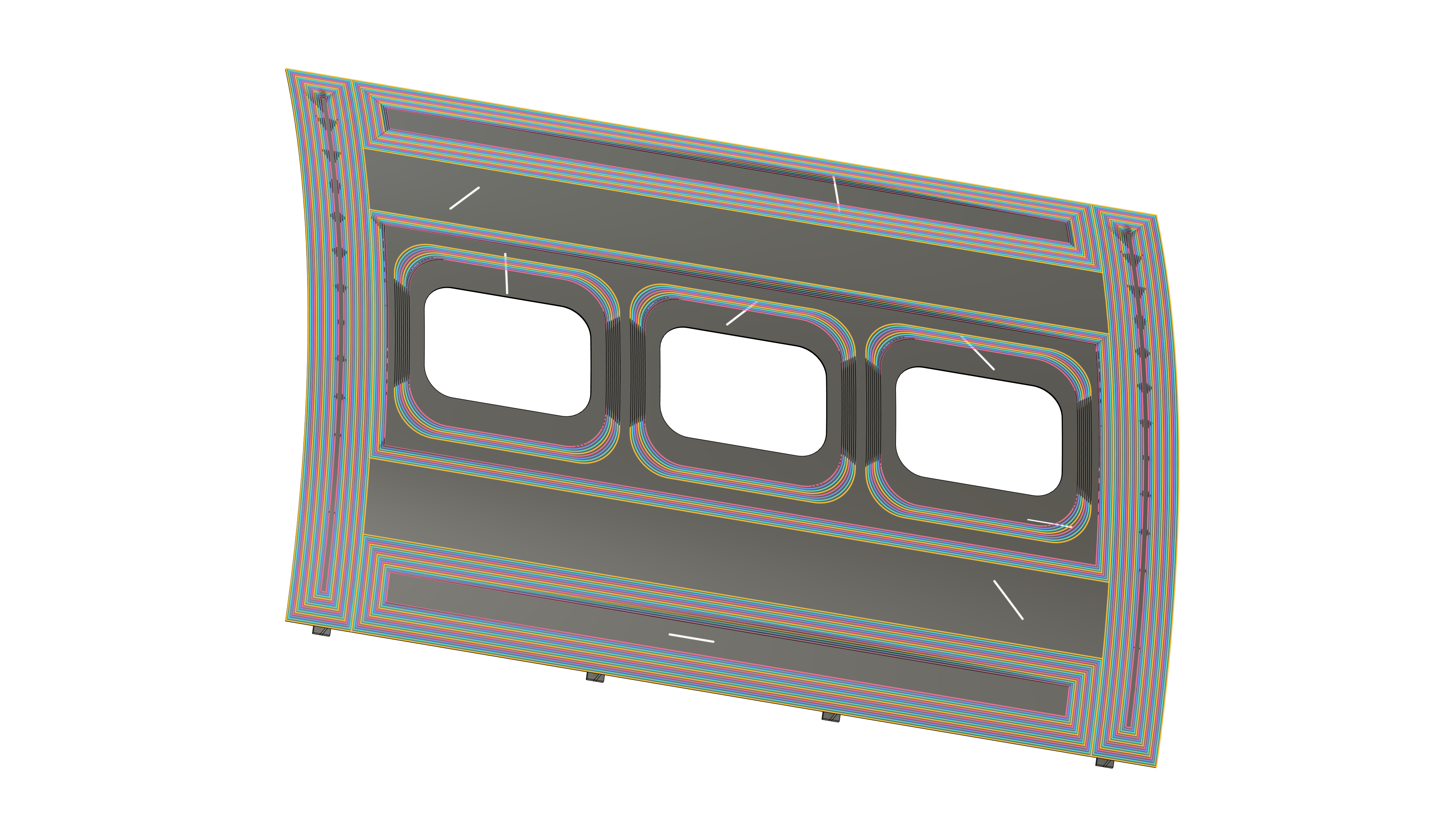
Original curved Fusion geometry informed by NASA ATCAS window reinforcement concepts. Three rounded windows, four frames and four stringers provide installation context. The full native archive separately retains 112 physical ply solids.
Download imported CADDownload base laminateDownload complete project
Select the lightweight outer support
Start from CAD. Inspect the three openings and frame/stringer context. Select cylindrical F28, with 3,524,758.176 mm² area, as the layup support. Keep the inner skin and installation-context faces outside the group.
Review evidence: The support STEP contains one trimmed skin and twenty context bodies; its 150 face identities survive the portable round trip. The full ply-assembly STEP is a separate inspection artifact.
Read the axial datum and sixteen base plies
Open the 16-ply skin. Read M56 AS7 UD134 at 0.134 mm, axial +Z zero in case04-axial-z, and TOOL_TO_BAG order. Inspect [45,0,−45,90,90,−45,0,45] repeated twice.
Review evidence: The continuous skin has 2.144 mm nominal gauge. The curved rosette stores a declared reference; it does not evaluate fabric transport.
Expand eight zones into ninety-six nested masks
Open the complete design. Compare BELT, UPPER/LOWER splice bands, LEFT/RIGHT end bands and WIN1–3. Each reinforcement ply has its own region, inset 5.5 mm from its predecessor; inspect its YZ boundary projected along X.
Review evidence: The design contains 112 records and 105 regions, including eight nominal zone references. Revised outer window pads are 560×620 mm with R110 corners, leaving 30 mm axial clearance between neighbors. Actual CAD windows remain holes. Polygon pad arcs differ by at most about 0.13 mm from the analytic native arcs.
Build and isolate a physical reinforcement
Use Exploded layers at 20 · inspect with a small gap. Isolate successive BELT and WIN2 plies, then compare their outlines around the opening. Use Build through ply to inspect the stagger, and Show all plies to restore context.
Review evidence: The mask shrinks with each drop. Interior belt points can carry twenty-four plies and full pad or band interiors thirty-two; those counts apply at the verified locations below.
Find the narrow edge exceptions
In Thickness section use YZ projection, along Y, at Z≈1200 mm. Read the coverage beside window 2. Compare the receipt samples at Y=450, 320, 200, −358 and −347 mm. A display section may undersample a narrow 5.5 mm interval; use the exact authored footprint coordinates for review.
Review evidence: Plain skin: 16/2.144 mm; full belt: 24/3.216 mm; full pad: 32/4.288 mm. At Y=−358 the 17-ply/2.278 mm stack fails symmetry and balance. At Y=−347 the 19-ply/2.546 mm stack fails symmetry and passes balance. The window centre has no laminate.
Review termination pairing and preserve the checked design
Save a belt-drop review copy. Compare the original ply terminations, propose mirrored-pair termination or a changed order, and re-evaluate spatial stacks. Keep assigned-region checks, whole-family checks and local overlap checks distinct. Check the solid ligaments at Y0/Z875 and Y0/Z1525 mm: each carries the 24-ply belt, with no coincident neighboring pad plies. Regenerate sheets, save, reopen and export the revision.
Review evidence: Complete family interiors can pass while the staggered edge fails. A one-ply region result describes its assigned sequence, not the entire overlapping stack. Revised geometry sampling checks 34,128 solid-skin points: maximum 32 plies/4.288 mm and zero duplicate radial levels. Nominal prepreg usage is 17.1285 kg at 206 gsm, before scrap or trim allowance.
Edit and review exercise
Record the 17-ply edge finding before changing anything. Propose a paired termination in a saved revision, then verify symmetry, balance, gauge and window clearance at each affected edge interval. Keep the original failure evidence.
Case 05
Compound-curved frame bracket
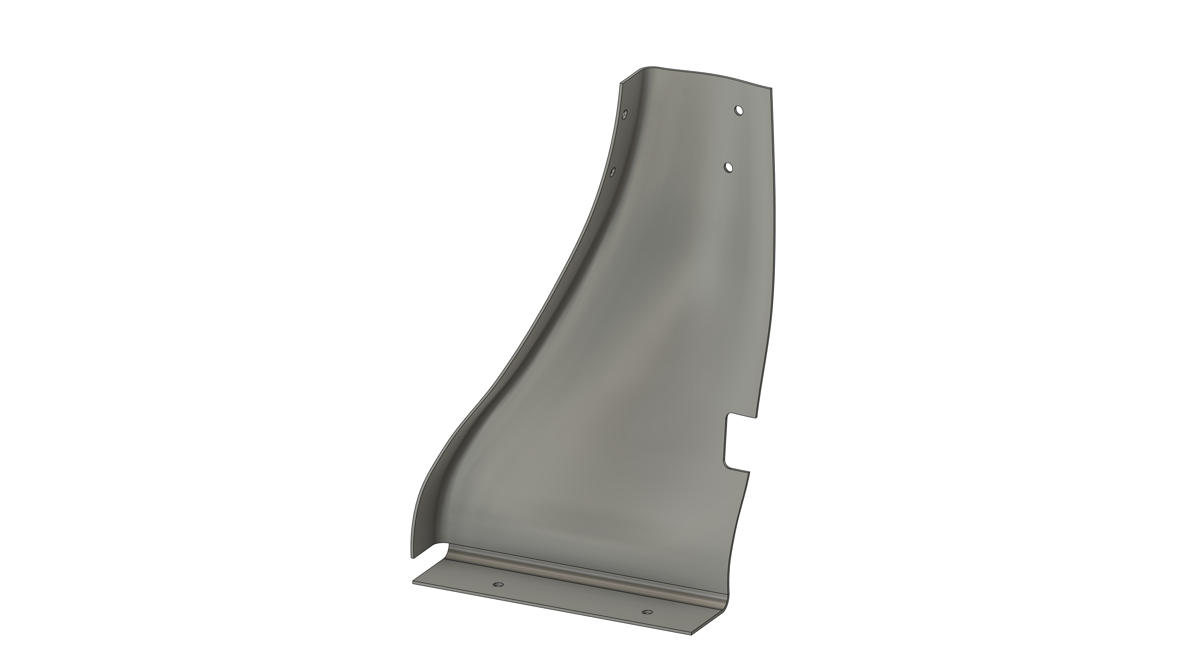
Original Fusion geometry follows the supplied curved-frame reference. Its web has camber and sweep, an integral return, a radiused foot and six mounting holes. The eight-ply fabric stack follows Luinge & Warnet (2020); local pads are authored.
Download imported CADDownload base laminateDownload complete project
Identify the connected curved support
Start from CAD and orbit the web, return and foot. In Model, inspect F23 outer web/return, F18 foot bend and F14 outer foot. Inspect all six real diameter-8 mm holes.
Review evidence: The native carrier is one healthy solid with twenty-five faces. The tooling region groups three retained outer support faces; their identities remain separate.
Read the woven material and two datums
Open the eight-ply primary laminate. In Materials, read TC1100 T300/PPS 5H Satin at 0.3 mm. Inspect warp angles [0,45,−45,0,0,−45,45,0]. In Rosette, compare the declared upright +Z reference with the foot-reinforcement datum: +X zero, −Z normal.
Review evidence: Eight woven plies give 2.4 mm nominal gauge; each ply also contains a second yarn family at warp+90°. The primary +Z reference is normal to horizontal F14 and is not an evaluated in-plane direction there. The +X foot datum applies to reinforcement. Undocumented areal mass and process values remain unspecified.
Define foot and upper-web reinforcement
Open the complete design. Inspect the foot XY patch, X45–235/Y−60–−20 mm, clipped to F14; compare the upper-web XZ patch, X180–267/Z325–420 mm, clipped to F23.
Review evidence: Three regions carry sixteen records. Each pad adds four [45,−45,−45,45] plies, split before and after the primary stack. The disjoint reinforced locations each have twelve contributing plies and 3.6 mm gauge.
Isolate the pads and mounting openings
Use Exploded layers, a moderate gap, and Play layup. Isolate a foot ply and both real holes; then isolate an upper-web ply and orbit its curved footprint. Return to Show all plies.
Review evidence: The foot clip measures 7,499.469035 mm²: the 7,600 mm² rectangle minus two radius-4 mm holes. The upper-web clip measures 8,316.963868 mm² on the curved support.
Section the two local gauge changes
For the foot, use Thickness section: XY, along X, Across Y≈−35 mm. For the web, use XZ, along X, Across Z≈375 mm; then move below Z325 mm. Read the coordinate outputs and any projection ambiguity.
Review evidence: A clear section shows the nominal 2.4→3.6→2.4 mm change at the pad. The foot line avoids bolt centres at Y−42 mm. Assigned-region symmetry and balance pass; these checks do not evaluate transported yarn axes.
Save the checked design and prepare a handoff copy
Save and reopen the complete checked project. For design-intent export, preserve that original and create an explicitly named export copy if a representation guard requires it. Remove rule requirements only in the export copy and review the resulting package basis.
Review evidence: The genuine version-1.2 handoff was produced from a separate copy because that format cannot represent stacking-rule requirements. Three selected support faces and their mappings were independently reimported; no solved drape or machine program is included.
Edit and review exercise
Change one foot-pad warp angle in a saved copy and inspect the rule change. Restore it, then compare the upper-web section above and below Z325 mm. Explain which datum is meaningful on the horizontal foot.
Design and display basis
These projects retain genuine CAD support geometry, CAD-clipped footprints, material records, declared orientations and editable sequences. Layer offsets, magnification and exploded gaps are inspection displays. Thickness sections sample tessellated footprints and add declared ply thickness; projection ambiguity or a narrow transition can limit what the diagram resolves.
Curved rosettes in these cases store engineering intent. They do not solve transported fibres, fabric shear, wrinkles, forming, cure distortion or AFP steering, gaps and overlaps. Woven references have two yarn families. Manufacturing validation needs the actual material/process data, machine limits and results for the reviewed revision.
Assigned-region stacking checks compare the records assigned to one region. Whole-family checks and spatial overlap samples answer separate review questions. Keep the case04 edge failures and case01 drop/cutout findings in the review log. These teaching designs and typical supplier values do not establish an aerospace qualification.
Export formats may not represent every authored requirement. Case05 retains a checked complete project and a separately named handoff copy with rule requirements explicitly removed. A successful portable round trip demonstrates retained data; a manufacturing handoff also needs its geometry mapping and representation summary reviewed.
Sources and acknowledgments
- Siemens Fibersim feature references provide the five supplied visual feature intents. The authored cases are not exact reconstructions of the low-resolution images.
- NASA CRM-HL DLR geometry supplies the native case02 nacelle surface. Acknowledge Schmidt & Wild, AIAA 2024-2851, as requested by the DLR delivery note.
- Hexcel HexPly M56 supplier data supplies UD and woven typical properties. AS7 UD134 cured thickness is 0.134 mm; nominal total prepreg mass is 206 gsm, distinct from 134 gsm fibre mass.
- NASA fuselage-window frame study and NASA/Boeing ATCAS side-panel study, CR-4730 inform the case04 window reinforcement and assembly context. Its dimensions and stack are authored.
- Luinge & Warnet (2020) documents TC1100 T300/PPS fabric and the primary eight-ply reference used in case05. Applying that stack to this custom bracket and adding local pads are teaching choices.
- 4TU measured forming dataset and KIT industrial thermoforming benchmark are separate validation references. Their measured results belong to their own tools, materials and stacks.